Privacy statement: Your privacy is very important to Us. Our company promises not to disclose your personal information to any external company with out your explicit permission.
Accuracy of measurement results depends on the right method and precision instrumentation, and sometimes LEDs hidden in power outlets can cause unexpected measurement errors.
Previously, customers were using the PA310 power meter with a minimum current range of 5 mA. The wiring method is shown in Figure 1. The current value shows 1.9 mA. The customer test task requires measurement of standby power consumption. The 1.9 mA current on the instrument will have an impact on the measurement results. Where does 1.9 mA come from? How should I remove that?
The telephone communicates with the customer. It is recommended that the customer current channel not be connected to the measurement line, and the no-load current is zero. Initially suspected that the customer used the plug may have leakage current, but the customer troubleshooting measurement circuit has not found the cause. The next day, the customer brought the instrument and measurement system to our positioning problem. Our engineers found that this was the case. We tried to measure the current value from the live line and the neutral line to measure the current value, eliminating the influence of stray capacitance. After thinking about it, is there a current in the neutral and the live line? Is there a small load in the power socket? Shun vines, the culprit is actually an LED indicator on the plug!
After this case, we summarize and explain to the customer what needs to be paid attention to during the measurement:
1) The customer ignores the current of the LED indicator of the power strip when measuring.
2) When the measured loop current is small and the voltage is high, the current meter internal connection method is adopted;
3) The current measurement access point is located at the lower end of the potential (such as the neutral line) to prevent stray capacitance from generating leakage current.
When measuring the standby power consumption, in order to facilitate the measurement, the user will use the power strip for wiring, as shown in Figure 1, so the wiring must pay attention to the following three points:
1. Is there an LED indicator on the power strip, and if so, the current of this indicator is measured as the load current. The plug-in wiring is shown in Figure 1. Most of the plugs will have LED indicators. The current flowing through the LEDs after power-on is generally mA level. Therefore, it will bring errors to the measured current, especially the standby power consumption. Big.

Figure 1 plug wiring
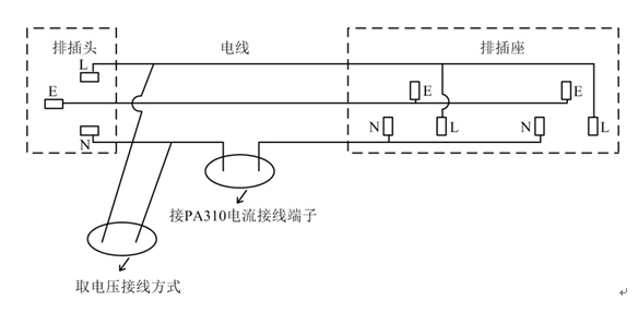
2. There are two ways to measure the voltage, as shown in Figure 2.

Figure 2 Take the voltage wiring method
The PA310 voltage measurement input impedance is 2MΩ. If the measured voltage is 220V, the current flowing through the voltage measurement terminal is 0.11mA. If the voltage is measured in mode 1, the current of 0.11 mA will not be measured by PA310, and if the voltage is measured by mode 2, as in the case of the LED indicator, this 0.11 mA is measured to make the measurement standby power consumption. The error increases.
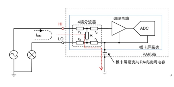
3. The current channel is connected to the high end and the low end. The measurement results are also different. There are some stray capacitances between the internal board shielding case and the case (there are capacitors in the two insulated conductors in the space). If the current channel is connected to the high end. The leakage current (red mark line in Figure 3) is generated, so the current measurement input should be stringed at a lower common mode voltage (lower side).

Figure 3 Current channel access to the high end to generate leakage current
In summary, since the current value measured by the standby power consumption is very small, care must be taken in wiring to avoid introducing additional errors. Recommended wiring for standby power measurement is shown in Figure 4.

Figure 4 Recommended power consumption for standby power measurement
Although the use of the power strip can achieve the purpose of measuring wiring, but the exposed wires not only bring security risks, but also lead to staggered wires, easy to connect wrong. The ZLG JXH10A junction box is perfect for solving these problems.
Therefore, in the high-precision measurement, in addition to the use of high-precision measuring instruments, the correct measurement method is required. A good measurement method will do more with less.
November 21, 2022
September 29, 2022
August 10, 2024
April 30, 2024
September 29, 2024
November 18, 2023
Bu tedarikçi için e-posta
November 21, 2022
September 29, 2022
August 10, 2024
April 30, 2024
September 29, 2024
November 18, 2023

Privacy statement: Your privacy is very important to Us. Our company promises not to disclose your personal information to any external company with out your explicit permission.

Fill in more information so that we can get in touch with you faster
Privacy statement: Your privacy is very important to Us. Our company promises not to disclose your personal information to any external company with out your explicit permission.